- Turning accuracy
Turning refers to the cutting process in which the workpiece rotates and the turning tool moves in a straight line or a curve in the plane to process the inner and outer cylindrical surfaces, end surfaces, conical surfaces, forming surfaces and threads of the workpiece.
The surface roughness of turning is 1.6-0.8 μm.
Rough turning requires a large depth of cut and large feed to improve turning efficiency without reducing the cutting speed, and the surface roughness is required to be 20-10um.
The semi-finishing and finishing turning should use high-speed and small feed and cutting depth as much as possible, and the surface roughness is 10-0.16um.
The finely ground diamond turning tool used on the high-precision lathe can finely turn non-ferrous metal workpieces at high speed with a surface roughness of 0.04-0.01um. This turning is also called “mirror turning”.
- Milling accuracy
Milling is a highly efficient machining method in which a rotating multi-blade tool is used to cut a workpiece. It is suitable for processing planes, grooves and special surfaces such as splines, gears and thread molds.
The machining accuracy of milling generally has a surface roughness of 6.3-1.6 μm.
The surface roughness during rough milling is 5-20 μm.
The surface roughness of semi-finish milling is 2.5-10 μm.
The surface roughness during fine milling is 0.63-5μm.
- Planing accuracy
Planing is a cutting method in which a planer is used to make a horizontal relative linear reciprocating motion on the workpiece, which is mainly used for the shape processing of parts.
The surface roughness of planing processing is Ra6.3-1.6μm.
Rough planing surface roughness is 25-12.5μm.
The semi-finishing surface roughness is 6.2—3.2 μm.
The surface roughness of finishing planing is 3.2-1.6 μm.
- Grinding accuracy
Grinding refers to the processing method of using abrasives and abrasive tools to remove excess material on the workpiece. It belongs to finishing and is widely used in the machinery manufacturing industry.
Grinding is usually used for semi-finishing and finishing, and the surface roughness is generally 1.25-0.16 μm.
The surface roughness of precision grinding is 0.16-0.04μm.
The surface roughness of ultra-precision grinding is 0.04-0.01μm.
The surface roughness of mirror grinding can reach below 0.01μm.
- Boring
It is an inner diameter cutting process in which a tool is used to enlarge a hole or other circular contour. Its application range is generally from semi-roughing to finishing. The tool used is usually a single-edged boring tool (called a boring bar).
The boring accuracy of steel materials can generally reach 2.5-0.16μm.
The machining accuracy of precision boring can reach 0.63-0.08μm.
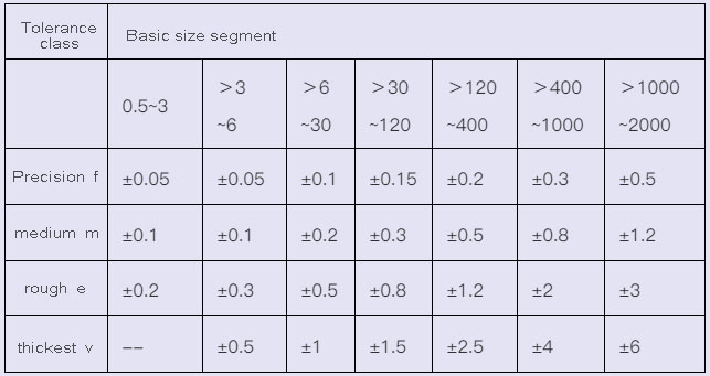
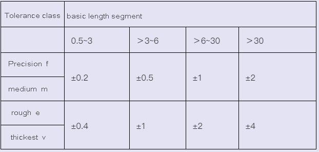
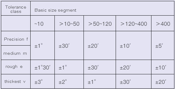
Free tolerance table
1.Limit deviation value of linear dimension (GB/T1804-2000) (mm)
2.Limit deviation of rounding radius and chamfering height dimension (GB/T1804-2000) mm
3.The limit deviation value of the angle dimension (GB/T1804-2000)
4.Tolerance of unmarked shape and position shall be in accordance with GB/T1184-K
4.1 Straightness and flatness without tolerance value (GB/T1184-1996) (mm)
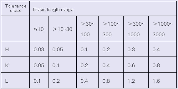
4.2 Verticality without tolerance value (GB/T1184-1996) (mm)
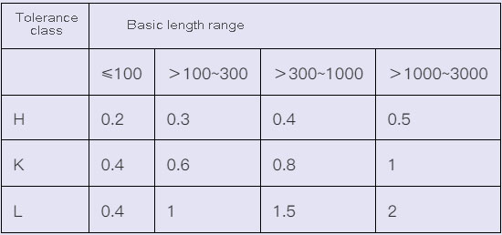
4.3 Symmetry without tolerance value (GB/T1184-1996) (mm)
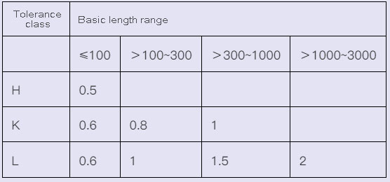
4.4 Unmarked tolerance value of circular runout (GB/T1184-1996) (mm)
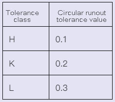
- Surface roughness
The surface of the parts should be marked with the level of roughness. If more surfaces have the same surface roughness grade, they should be marked in the upper right corner of the drawing, and the word “rest” should be added.
The choice of roughness grade can generally be determined according to the working requirements of each surface and the dimensional accuracy grade. Under the condition that the working requirements are met, the grade shall not be increased arbitrarily.
1) Selection of sampling length and evaluation length (GB/T1031-1995)
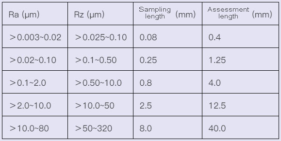
2) The numerical value of the arithmetic mean deviation Ra of the contour (GB/T1031-1995) (μm)
Series 1 0.012, 0.025, 0.050, 0.10, 0.20, 0.40, 0.80, 1.60, 3.2, 6.3, 12.5, 25, 50, 100
Series 2 0.008, 0.010, 0.016, 0.020, 0.032, 0.040, 0.063, 0.080, 0.125, 0.160, 0.25, 0.32, 0.50, 0.63, 1.0, 1.25, 2.0, 2.5, 4.0, 5.
8.0, 10.0, 16.0, 20, 32, 40, 63, 80
Note: Try to choose the 1st series
3) The value of the maximum height Rz of the contour (GB/T1031-1995) (μm)
Series 1 0.025, 0.050, 0.100, 0.20, 0.40, 0.80, 1.60, 3.2, 6.3, 12.5, 25, 50, 100, 200, 400, 800, 1600,
Series 2 0.032, 0.040, 0.063, 0.080, 0.125, 0.160, 0.25, 0.32, 0.50, 0.63, 1.0, 1.25, 2.0, 2.5, 4.0, 5.0, 8.0, 10.0, 16.0, 20, 32,
40, 63, 80, 125, 160, 250, 320, 500, 630
